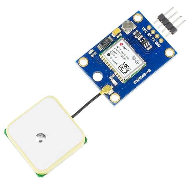
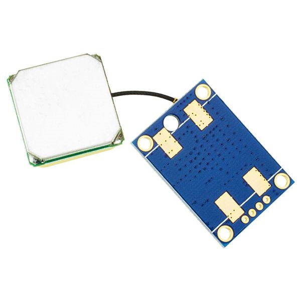
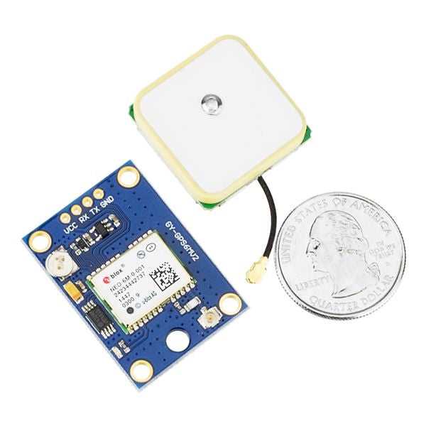
The NEO-6M is a very capable GPS for the price and size. Compatible with UART capable devices including Arduino, Raspberry Pi, MSP430, and MSP432.
Power the module and it will automatically acquire satellite signals and a position fix. Once it has a position fix the module will blink the on-board LED. This LED will continue to blink while the module has a position fix.
For a more advanced module check out our NEO-M8N GPS / GNSS Module.
Product Contents
- 1 - u-blox NEO-6M GY-GPS6MV2 GPS module with on board EEPROM
- 1 - GPS antenna
- 1 - 1x4 male header
Specifications
- Input Supply Voltage Range: 3.3V-6V, on board voltage regulator maintains 3.3V
- I/O Maximum Logic Level: 3.6V
- We have tested it with direct connection to the 5V serial pins on an Arduino and found it to work fine but extended periods of time may be different
- To use with a 5V logic device, such as an Arduino, we suggest level shifting the 5V TX signal using one of the following:
- Two 1N4148 diodes in series between the TX pin on your 5V device and the RX pin on this GPS module (will drop voltage to ~3.6V)
- Only recommended for baud rates of 9600 and less
- Only recommended for baud rates of 9600 and less
- Use a logic level converter module such as the Addicore Bi-Directional Logic Level Converter
- Two 1N4148 diodes in series between the TX pin on your 5V device and the RX pin on this GPS module (will drop voltage to ~3.6V)
- We have tested it with direct connection to the 5V serial pins on an Arduino and found it to work fine but extended periods of time may be different
- WAAS (Wide Area Augmentation System) enabled GPS unit
- <1 second to first fix (TTFF) for hot starts
- 27 seconds to first fix (TTFF) for cold starts
- On board LED will blink after module acquires a position fix and will continue blinking as long as the module has a fix
- 50 Channel NEMA GPS receiver
- UART: 9600 baud by default, but is configurable from 4800 to 115200 baud
- 5Hz max update rate
- External EEPROM for configuration storage
- Four plated mounting holes, 3mm in diameter
- One additional non-plated mounting/antenna cable hole, 4mm in diameter
- Position Accuracy: 2 m and better with multiple good satellite signals
- Velocity Accuracy: 0.1 m/s
- Maximum Velocity: 500 m/s
- Heading Accuracy: 0.5 degrees while moving
- On board battery for battery backed RAM (BBR)
- Battery is recharged through a simple diode and resistor charger circuit from the on-board voltage regulator's 3.3V output
- Battery is recharged through a simple diode and resistor charger circuit from the on-board voltage regulator's 3.3V output
- Three different power modes (refer to Receiver Description Including Protocol Specification for information on configuring the operating mode)
- Two continuous operating modes:
-
Maximum Performance Mode - continuously uses the acquisition engine, resulting in the best possible time to first fix (TTFF)
-
Eco Mode - optimizes the use of the acquisition engine to minimize current consumption
-
Maximum Performance Mode - continuously uses the acquisition engine, resulting in the best possible time to first fix (TTFF)
- One intermittent operating mode
-
Power Save Mode - draws only 11mA - Utilizes cyclic tracking, with configurable update periods, which reduces the average power consumption significantly
-
Power Save Mode - draws only 11mA - Utilizes cyclic tracking, with configurable update periods, which reduces the average power consumption significantly
- Two continuous operating modes:
- -156dBm Hotstart sensitivity
- Dimensions of GPS Module: 36mm (1.42in) x 25.8mm (1.02in) x 4mm (0.16in)
- Dimensions of Antenna: 25.5mm (1in) x 25.5mm (1in) x 8.8mm (0.35in)
Resources
- u-blox Provided Resources:
- On board M24C32-R (432RP marking) EEPROM Datasheet
- On board voltage regulator MIC5205 (marked KB33) Datasheet
-
Arduino NEO-6M Library
-
Raspberry Pi Tutorial (Instructables)
- u-center a u-blox test program for Windows (requires a USB to UART conversion module or dongle such as our CP2102 module)

