
ESP8266 D1 Mini WiFi Dev Board
The D1 Mini is a breadboard-compatible WIFI development board based on the ESP8266.
This board is compatible with the Arduino IDE and with NodeMCU.
All of the I/O pins have interrupt, PWM, I2C, and one-wire capability, except for pin D0.
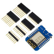
The board comes with three different sets of header pins: long-pin female headers, standard-pin female headers, and male pin headers. You can solder the set you choose to your board. The long-pin female headers are our favorite since they allow you to plug the board into a breadboard while also having female headers available on top of the board.
The board includes an on-board USB Micro connector and USB to serial (UART) converter, making it easy to power and program the board by simply connecting it to your computer with a USB Micro cable.
We offer a board similar to this called the ESP8266 D1 R2 V2.1.0 WiFi Dev Board that is shaped like the common Arduino UNO footprint.
Note: The D1 Mini is a 3.3V device. If you connect it to 5V digital sensors or devices you may need a logic-level converter, such as our 4-channel or 8-channel logic-level converter modules.
Product Contents
- 1 - D1 Mini ESP8266 Dev Board
- 2 - Long-Pin Female Header 1x8
- 2 - Standard-Pin Female Header 1x8
- 2 - Male Pin Header 1x8
Specifications
- Microcontroller: ESP8266
- USB ↔ Serial Converter: CH340G
- Digital I/O Pins: 11 (see note 1 below)
- Analog Input Pins: 1
- Flash Memory: 4MB
- Board Dimensions (not including pins)
- Length: 34.2 mm (1.35")
- Width: 25.6 mm (1.01")
- Height: 7 mm (0.28")
- Length: 34.2 mm (1.35")
Note 1: All I/O pins have interrupt, PWM, I2C, and one-wire capability, except for D0
Bottom View
(Click on image to view full size)

Top View
(Click on image to view full size)

Three Header Options
- Use the provided sets of header pins to configure your board how you desire.
Long Female Headers
(Click on image to view full size)

Female Headers
(Click on image to view full size)

Male Headers
(Click on image to view full size)

Pinout
(Click on image to view full size)

Pins
- Board Pin - Function - ESP8266 Pin
- TX - TXD - TXD
- RX - RXD - RXD
- A0 - Analog input - A0
- D0 - I/O - GPIO16
- D1 - I/O, SCL - GPIO5
- D2 - I/O, SDA - GPIO4
- D3 - I/O, 10k pull-up - GPIO0
- D4 - I/O, 10k pull-up, BUILTIN_LED - GPIO2
- D5 - I/O, SCK - GPIO14
- D6 - I/O, MISO - GPIO12
- D7 - I/O, MOSI - GPIO13
- D8 - I/O, 10k pull-down, SS - GPIO15
- G - Ground - GND
- 5V - 5V
- 3V3 - 3.3V - 3.3V
- RST - Reset - RST
- TX - TXD - TXD
- All I/O pins have interrupt, PWM, I2C, and one-wire capability, except for D0
Dimensions
(Click on image to view full size)

Resources
- CH340G Driver:
- You will need to install a driver for your computer to recognize the on-board CH340G USB to serial converter. If you are using Codebender online you do not need to install a driver.
-
Windows Driver (Automatic Installer)
-
Mac OS Driver
-
Linux Driver
- You will need to install a driver for your computer to recognize the on-board CH340G USB to serial converter. If you are using Codebender online you do not need to install a driver.
- ESP8266:
-
D1 Mini Board Schematic
-
Example sketch for fading on-board LED (.zip download)
- We flash this onto each board before shipping them to you