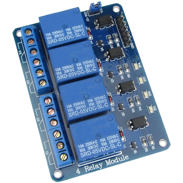

4 Channel Relay Module
4 Channel Relay Module. Uses optocoupler driven relays to switch higher voltage and/or current applications with an Arduino, Raspberry Pi, Beaglebone, or other microcontroller or ARM boards.
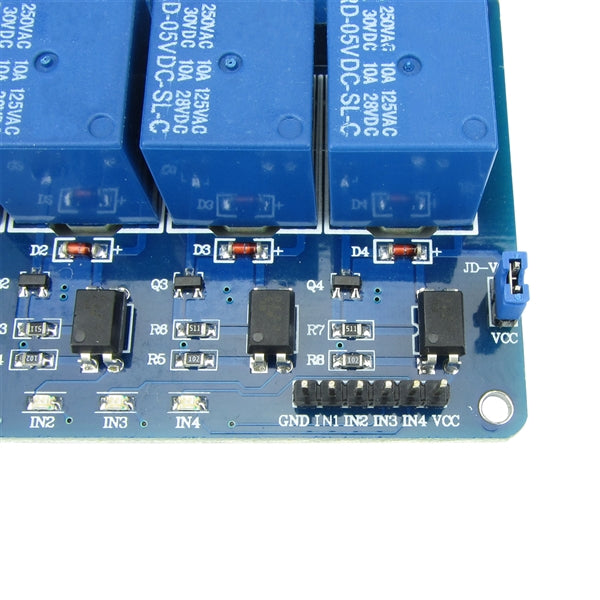
Inputs are opto-isolated to protect your controller or control circuits.
Inputs are active low triggered -- to activate one of the relays requires the input pin being pulled to ground (GND).
You can find 3D printable enclosures for this module on Thingiverse, such as this 4-Channel Relay Module Case.
WARNING: The screw terminals and relay solder connections are exposed on the bottom of the board. Caution must be used especially when using this module with high voltages, such as mains power or any voltages greater than 12V. Always disconnect high voltage from the module before wiring or touching the module. When high voltage is supplied to the module be sure to refrain from touching or pointing to any part of the module. Working with high voltages should only be undertaken by experienced individuals.
Specifications
- Supply Voltage: 3.75 to 6 V
- Supply Current with Relays De-Energized: 0.1 mA
- Supply Current with 1 Relay Energized: 68 mA
- Supply Current with 2 Relays Energized: 127 mA
- Supply Current with 3 Relays Energized: 182 mA
- Supply Current with 4 Relays Energized: 231 mA
- Input Control Signals: Active Low
- Input Control Signals Current: 1.95 to 2 mA per Channel
- Relay Max Contact Voltage: 250 VAC or 30 VDC
- Relay Max Contact Current: 10 A
- Dimensions
- Size 1
- Length: 72 mm (2.83")
- Width: 52 mm (2.04")
- Height: 17 mm (0.67")
- Length: 72 mm (2.83")
- Size 2
- Length: 75.5 mm (2.97")
- Width: 55 mm (2.17")
- Height: 17 mm (0.67")
- Length: 75.5 mm (2.97")
- Size 3
- Length: 75 mm (2.95")
- Width: 50 mm (1.96")
- Height: 17 mm (0.67")
- Length: 75 mm (2.95")
- Size 1
Resources